
Time: Oct 28 2026 Views: 7
A Manufacturer's Guide to Custom Gear Segments for Rotary Kilns, Ball Mills and Heavy Industrial Drives
Large industrial gear segments are critical components in heavy-duty transmission systems. They are commonly used to form segmented girth gears in rotary kilns, ball mills, grinding mills and other large rotating equipment.
When an industrial gear segment becomes worn, cracked or damaged, replacing it is rarely as simple as manufacturing a new casting with the same external dimensions.
The replacement must satisfy several requirements:
1. Suitable material grade and heat treatment
2. Reliable casting integrity
3. Accurate tooth geometry
4. Precision-machined segment joints
5. Controlled radial and axial runout
6. Correct meshing with the existing pinion
For maintenance engineers and equipment purchasers, understanding these requirements can help prevent installation problems, premature gear wear and costly shutdowns.
This guide explains how custom segment gears are manufactured and what customers should verify before placing an order.
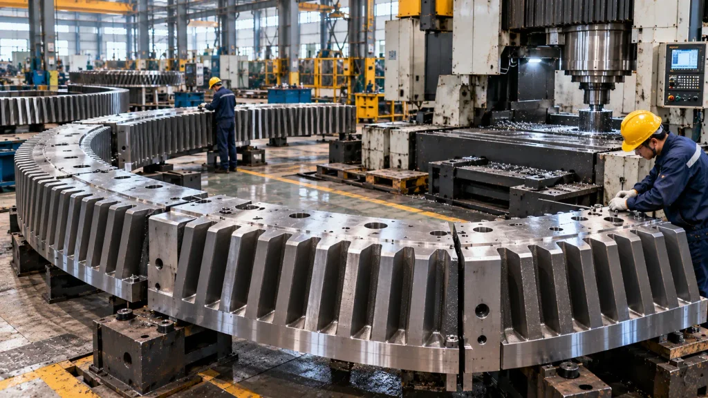
A segment gear is a portion of a gear rather than a complete circular gear.
The term can describe different industrial designs. In some mechanisms, it refers to a sector-shaped gear used for limited-angle movement.
In heavy mining and cement equipment, however, the term often refers to an individual section of a large segmented ring gear.
These components are more precisely called:
The correct term depends on whether the customer requires a complete gear assembly or an individual replacement segment.
| Equipment | Gear Application | Main Function |
| Rotary Kiln | Segmented girth gear | Drives kiln shell rotation |
| Ball Mill | Split girth gear | Transmits torque to the grinding mill |
| Geared SAG Mill | Large girth gear | Drives the mill shell |
| Rotary Dryer | Segmented ring gear | Rotates the drying drum |
| Selected Mining Shovels | Swing gear segments | Supports the swing-drive system |
For rotary kilns and grinding mills, the girth gear normally operates with one or more pinions.
This gear-and-pinion relationship is fundamental to replacement-part compatibility.
Material selection is one of the first engineering decisions in segment gear manufacturing.
Large girth gears operate under high torque, repeated loading and demanding industrial conditions.
Their materials must provide an appropriate balance of strength, toughness, wear resistance and machinability.
| Material Grade | Material Type | Typical Engineering Considerations |
| ZG310-570 | Cast carbon steel | General-duty applications where the design permits |
| ZG35CrMo | Cast chromium-molybdenum alloy steel | Strength and toughness for heavy-duty gears |
| ZG42CrMo | Cast chromium-molybdenum alloy steel | Higher-strength applications subject to specified heat treatment |
| ZG35CrNiMo | Cast nickel-chromium-molybdenum alloy steel | Applications requiring suitable toughness and strength |
| 42CrMo4 | Wrought alloy steel | Forged gear components where the geometry and manufacturing route permit |
These are examples of materials encountered in industrial gearing, not interchangeable specifications.
Cast and wrought grades must not be treated as direct equivalents merely because their names or alloying elements are similar.
No.
A gear segment with excessive hardness but insufficient toughness may be vulnerable to cracking under impact or bending loads.
Conversely, inadequate hardness or strength can contribute to tooth wear or surface fatigue.
The appropriate material and heat treatment depend on:
Manufacturer's recommendation: If the existing gear has operated successfully for many years, begin by identifying its original material specification and failure history before proposing a different alloy.
A material upgrade should be supported by engineering calculations and compatibility evaluation, not simply by a higher hardness number.
For large cast-steel gear segments, internal casting quality is as important as the finished tooth surface.
A segment may look dimensionally correct after machining but still contain internal discontinuities that affect its structural reliability.
The melting process must achieve the specified chemical composition.
Uncontrolled variations in carbon or alloying elements can affect hardenability, mechanical properties and heat-treatment response.
Large gear segments have substantial differences in section thickness.
Casting engineers must design the mould, risers and feeding system to control shrinkage and promote sound solidification.
Heat treatment is used to achieve the required mechanical properties and manage residual stresses.
The selected process depends on the material grade, component dimensions and engineering requirements.
Inspection requirements may include:
The testing method, coverage and acceptance criteria should be specified in the purchase documentation.
For critical custom gear segments, consider requesting:
These documents provide evidence of compliance with agreed requirements.
Gear teeth must transmit torque smoothly through controlled contact with the mating pinion.
A replacement segment can have the correct outside diameter and number of teeth but still perform poorly if its tooth geometry is inaccurate.
Important parameters include:
Module
The module defines tooth size in a metric gear system.
Pressure Angle
The pressure angle affects tooth geometry and the direction of transmitted forces.
Tooth Profile
Profile accuracy influences how the teeth engage throughout the mesh cycle.
Pitch Accuracy
Pitch deviations can create irregular tooth engagement and dynamic loading.
Lead or Helix Accuracy
For helical gears, the helix geometry must be correct. For spur gears, tooth alignment across the face width remains important.
Tooth Thickness
Incorrect tooth thickness affects backlash and meshing compatibility.
Depending on gear size, geometry and available equipment, production may involve:
The manufacturing route must be selected to achieve the specified gear accuracy.
If the new gear segment has a different tooth profile or pitch from the original gear, the pinion may not engage correctly.
Possible consequences include:
For replacement projects, the objective is not merely to manufacture a precise gear.
It is to manufacture a gear that is accurate and compatible with the existing drive system.
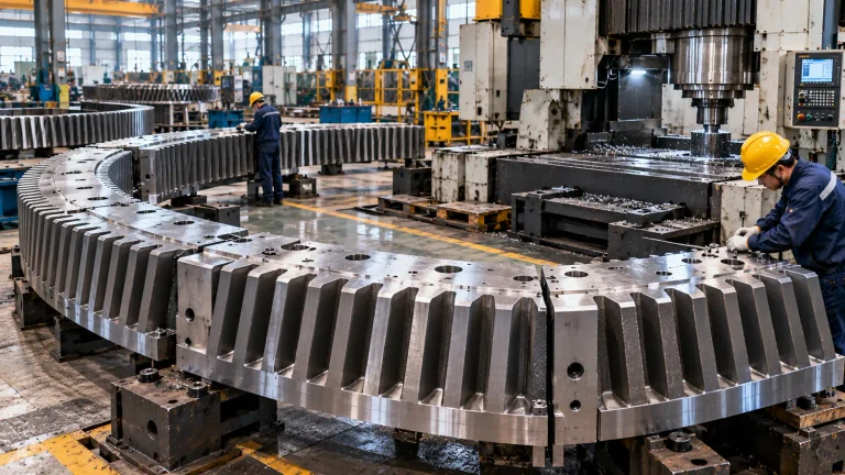
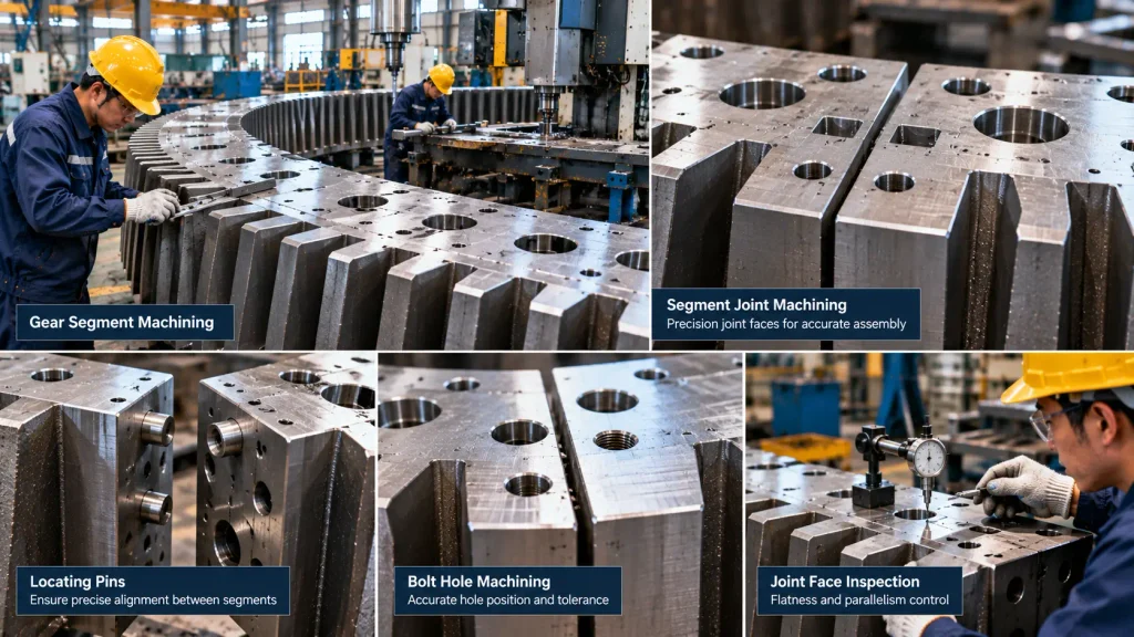
Large girth gears are often manufactured in separate sections because of casting, machining, transportation and installation constraints.
The individual sections are assembled to form a complete gear ring.
The joint between two segments is therefore a critical manufacturing feature.
The mating surfaces must fit according to the approved design.
Poor joint contact can create unwanted movement or deformation when the connecting bolts are tightened.
Joint bolt holes must be positioned and machined to the specified dimensions.
Incorrect hole locations can prevent assembly or introduce undesirable stresses.
Depending on the design, locating pins, fitted bolts or other features may help establish accurate segment positioning.
The tooth spacing and geometry must remain correct where adjacent segments meet.
A local pitch error at a joint can produce a repeated impact as the gear rotates.
Where specified, trial assembly can verify:
Trial assembly reduces the risk of discovering basic dimensional problems during an equipment shutdown.
However, factory trial assembly does not replace final alignment and inspection after installation.
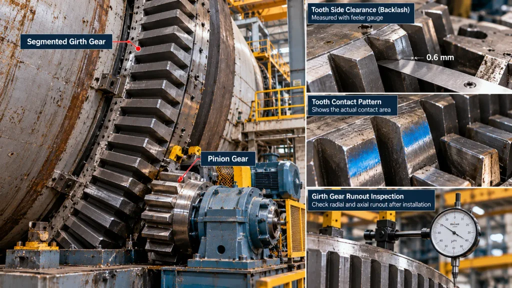
Runout is one of the most important inspection considerations for large assembled girth gears.
Radial runout describes variation in the gear's radial position relative to its intended rotational axis.
Excessive radial runout can contribute to variations in effective gear engagement and backlash as the ring rotates.
Axial runout describes variation in the gear's axial position during rotation.
Excessive axial movement or face runout can contribute to uneven tooth contact across the face width.
A girth gear with unacceptable installed runout may cause:
These measurements must be distinguished.
Factory inspection evaluates the manufactured gear under a defined setup.
Installed inspection evaluates the gear after it has been assembled and mounted on the actual machine.
Installed runout also depends on:
Therefore, a manufacturer and customer should agree in advance on the inspection setup, allowable deviations and responsibility for final site acceptance.
There is no single universal runout tolerance suitable for every segmented girth gear.
This is often the most important question in a custom replacement project.
A replacement gear segment must match the geometry of the existing gear system.
The manufacturer should verify:
| Parameter | Why It Matters |
| Module or diametral pitch | Ensures compatible tooth sizing |
| Pressure angle | Ensures compatible tooth geometry |
| Tooth count and pitch-circle geometry | Establishes correct ring geometry |
| Spur or helical configuration | Ensures matching tooth orientation |
| Helix angle and hand, if applicable | Ensures helical compatibility |
| Tooth thickness | Influences backlash |
| Face width | Affects contact area |
| Pinion condition | Determines whether the existing mating gear remains suitable |
| Center distance and alignment | Affect engagement and tooth contact |
Backlash is the clearance between mating gear teeth under defined measurement conditions.
Too little backlash may lead to interference under operating conditions.
Excessive backlash may increase impact loading and contribute to abnormal operation.
The acceptable range must come from the approved drive design and installation requirements.
Contact-pattern inspection helps determine whether the gear and pinion are engaging as intended.
An uneven contact pattern can indicate alignment, geometry or deformation problems.
Not necessarily.
If the pinion remains within acceptable wear and dimensional limits, it may be suitable for continued service.
However, a severely worn or damaged pinion can compromise the performance of a new gear segment.
The pinion should therefore be inspected before finalizing the replacement plan.
Manufacturer's recommendation: Never assume that a newly manufactured gear segment will mesh correctly with an existing pinion based on module and tooth count alone.
Illustrative engineering scenario — not a documented LANGTENG customer project.
A cement plant discovers cracking and severe tooth damage in one section of its rotary kiln girth gear.
The plant wants to replace only the damaged section to reduce replacement cost and shutdown time.
The remaining gear sections and original pinion are still installed.
The replacement must fit the existing ring assembly.
Before manufacturing, the supplier should confirm:
A suitable manufacturing plan may involve
Replacing one segment may not be technically appropriate if the remaining gear sections have excessive wear, incompatible tooth geometry or unacceptable structural condition.
In that case, replacing a larger portion of the gear—or the complete ring—may be necessary.
Key lesson: The lowest initial replacement cost is not always the lowest-risk solution.
Illustrative engineering scenario — not a documented LANGTENG customer project.
A mining operation requires a replacement girth gear for an older ball mill.
The original equipment manufacturer no longer supplies the component.
Only partial drawings and measurements from the existing gear are available.
The manufacturer must establish reliable design information before production.
The project may require:
Measurements from a worn gear can help reconstruct its geometry.
However, worn surfaces do not necessarily represent the original design dimensions.
Reverse engineering must therefore distinguish between original design features, manufacturing tolerances and service-related wear.
After engineering approval, the replacement gear can be manufactured in sections suitable for production, transport and installation.
Critical machining and inspection requirements should be agreed before production begins.
Reverse engineering is not simply copying a worn component.
It is the process of reconstructing a technically valid replacement specification.
Illustrative engineering scenario — not a documented LANGTENG customer project.
After installation of a replacement gear segment, a maintenance team observes abnormal noise and uneven tooth contact near the segment joint.
The problem may involve:
The maintenance and engineering teams should compare:
The findings should determine whether corrective action is needed in the gear segment, the installation or another part of the drive system.
A gear that passes dimensional inspection at the factory may still require careful alignment during installation.
Manufacturing accuracy and installation accuracy are both essential.
A well-prepared technical inquiry helps the manufacturer assess feasibility and avoid unnecessary clarification during production.
| Information | Purpose |
| Equipment type and model | Identifies the application |
| Original gear drawings | Defines design requirements |
| Gear module or DP | Establishes tooth size |
| Number of teeth | Establishes gear geometry |
| Pressure angle | Defines tooth profile |
| Pitch diameter | Supports dimensional verification |
| Face width | Defines gear tooth width |
| Material grade | Establishes material requirements |
| Heat-treatment requirements | Defines mechanical-property targets |
| Segment arrangement | Defines assembly configuration |
| Joint and mounting drawings | Establishes interface requirements |
| Pinion drawings or measurements | Supports compatibility assessment |
| Existing wear and damage photographs | Helps identify failure conditions |
| Required inspection standards | Defines acceptance requirements |
If complete drawings are unavailable, customers should provide the available dimensions, photographs and equipment information for an initial feasibility review.
For critical drive components, final manufacturing should proceed only after the technical requirements have been sufficiently verified and approved.
For heavy-duty segmented gears, supplier evaluation should go beyond casting capacity and price.
Important questions include:
Material control
Can the manufacturer provide the specified material grade and traceable test results?
Casting quality
Are the casting process and inspection requirements suitable for the component's size and duty?
Heat treatment
Can the required mechanical properties be achieved and documented?
Machining capability
Can the supplier machine the joint faces, mounting features and gear teeth to the required accuracy?
Inspection capability
Can the supplier verify tooth geometry, critical dimensions and applicable non-destructive testing requirements?
Assembly verification
Can the supplier demonstrate joint fit and assembled geometry where required?
Engineering communication
Can the supplier review existing pinion information, drawings and replacement compatibility concerns?
These questions help customers distinguish between suppliers that can produce a large casting and those capable of delivering a functionally compatible transmission component.
LANGTENG focuses on custom heavy industrial components for mining, cement, metallurgy and other demanding applications.
Our relevant manufacturing scope includes large steel castings, forgings and precision-machined components.
For custom gear segment inquiries, the engineering review can address:
Compatibility with existing equipment
Actual manufacturing feasibility depends on the component size, required accuracy, material grade, available production processes and approved technical specifications.
We encourage customers to provide original drawings whenever possible, especially for replacement segments intended to operate with an existing girth gear and pinion.
A segment gear is an individual portion of a gear. A segmented girth gear is a complete large ring gear assembled from multiple sections.
Sometimes, but not automatically. The remaining gear sections, joint interfaces and mating pinion must be evaluated for dimensional and functional compatibility.
Large industrial gear segments may be manufactured from cast carbon steel or cast alloy steel, including specified chromium-molybdenum and nickel-chromium-molybdenum grades.
The final material must follow the approved design requirements.
Inspection may include tooth profile, pitch, lead or helix, tooth thickness and other specified gear accuracy measurements.
Incorrect joint geometry can affect assembly fit, tooth continuity and the accuracy of the complete gear ring.
Possible contributors include manufacturing deviations, joint assembly errors, mounting problems, supporting structure deformation and installation misalignment.
It may, provided the tooth geometry, dimensions, operating conditions and existing pinion condition are compatible.
Compatibility must be verified rather than assumed.
Reverse engineering may be possible using existing parts, measurements and operating data.
However, critical design requirements must be established and approved before manufacturing.
Manufacturing a reliable industrial gear segment requires more than producing a large steel casting.
Material selection, casting integrity, heat treatment, tooth accuracy, segment joint machining and assembled geometry all influence the final result.
For replacement projects, compatibility with the existing gear and pinion is equally important.
The best approach begins with a clear technical specification, an assessment of existing equipment conditions and agreement on manufacturing and inspection requirements.
Need Custom Gear Segments for a Rotary Kiln or Grinding Mill?
LANGTENG welcomes inquiries for custom heavy-duty gear segments and industrial transmission components.
Send your drawings, material specifications, gear parameters and application details for a manufacturing feasibility review.
Request a Custom Segment Gear Quote
@ 2025-2026 Langteng Machinery