
Time: Oct 24 2026 Views: 25
Spiral bevel gears help transfer rotary motion between intersecting shafts, most often at a right angle, while keeping the motion smooth, compact, and efficient. Their curved teeth give them more gradual contact than straight bevel gears, which is why they are often used where quiet operation, durability, and controlled torque transfer matter. This article explains how they work, where they are used, and what to consider when selecting or discussing a spiral bevel gearbox, gear reducer, or custom gear set.
A spiral bevel gear is a cone-shaped gear with curved, angled teeth designed to mesh with another bevel gear on an intersecting shaft. Instead of meeting all at once, the teeth engage progressively across the tooth face, which helps reduce shock, vibration, and operating noise. This geometry makes the spiral bevel gear a strong choice for machinery that needs compact right-angle power transmission without rough engagement.
In simple terms, the gear changes the direction of rotation while carrying torque from one shaft to another. The “spiral” part refers to the curved tooth form, not a separate component. You may also see the term bevel gear spiral used in technical discussions to describe this curved-tooth geometry.
The key mechanical advantage of a spiral gear in bevel form is gradual tooth contact. In a straight bevel gear, tooth engagement can be more abrupt because contact begins across a relatively direct line. In a spiral bevel gear, contact starts at one end of the tooth and rolls across the surface, spreading load more smoothly.
This smoother engagement helps in three practical ways. First, it reduces impact forces during meshing, which can support longer service life when the gear is properly designed and lubricated. Second, it can lower vibration and noise compared with less refined tooth forms. Third, it allows compact gear arrangements for applications where space is limited but dependable torque transfer is still required.
The geometry is more complex than it looks. Tooth curvature, pressure angle, pitch cone, backlash, contact pattern, and mounting distance all influence how the gears run. Small changes in alignment can shift the contact pattern, so installation and housing precision are just as important as the gear itself.
Spiral bevel gear sets are used in many machines that need to redirect power between angled shafts. Their compact shape makes them useful in enclosed drives, mobile equipment, machine tools, packaging systems, marine equipment, and industrial automation. They can also appear in differential-style assemblies and specialized motion-control systems where smooth directional transfer is valuable.
A spiral bevel gearbox often uses one or more spiral bevel gear sets inside a housing to create a compact right-angle drive. Depending on the application, the gearbox may prioritize torque capacity, speed reduction, low noise, or space savings. A spiral bevel gear reducer performs a similar role when the main goal is reducing output speed while increasing usable torque at the driven shaft.
Typical selection priorities include:
Gear terminology can be confusing because similar phrases are sometimes used differently across industries. A spiral bevel gear is specifically a bevel gear with curved teeth on a conical pitch surface. A helical bevel gear is often used informally to describe bevel gearing with angled or curved tooth action, but in strict gear language, “helical” usually refers to cylindrical gears with angled teeth rather than conical bevel gears.
The phrase spiral gear can also have a broader meaning. Some people use it casually for any gear with a curved or angled tooth path, while others use it to describe worm-like or crossed-axis arrangements. In a purchasing or engineering conversation, it is best to confirm the shaft arrangement, tooth form, ratio, rotation direction, and load requirements rather than relying on the name alone.
Spiral gear design affects how quietly the gear runs, how much load it can carry, how efficiently it transfers torque, and how sensitive it is to misalignment. A well-designed gear set balances tooth strength, surface durability, contact pattern, manufacturability, and lubrication needs. The goal is not simply to make the teeth fit together, but to make them share load predictably under real operating conditions.
Several design factors deserve special attention:
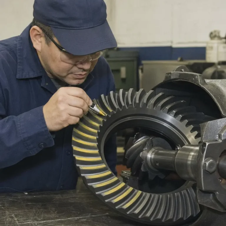
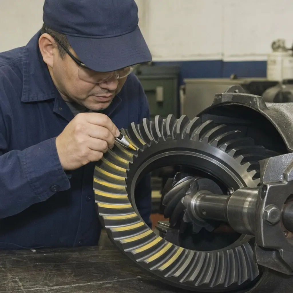
The curved tooth form determines how the gear pair engages. A desirable contact pattern typically avoids edge loading, where too much force concentrates near the end of the tooth. If the pattern is too far off-center, the gear may run louder, wear faster, or develop heat under load.
The gear ratio determines the relationship between input speed and output speed. In a reducer, a lower output speed usually comes with increased torque. The tooth size, face width, material, and heat treatment must support the expected load without making the assembly larger or more expensive than necessary.
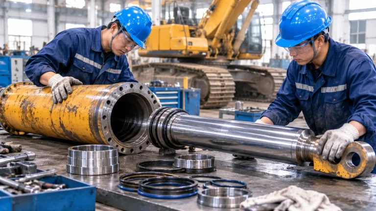
Even a precisely manufactured gear can perform poorly if it is mounted incorrectly. Bearing support, shaft deflection, housing stiffness, and assembly tolerances affect the final contact pattern. This is why high-quality spiral bevel gear systems require both good manufacturing and careful integration.
Lubrication reduces friction, carries away heat, and protects the tooth surface. The right lubricant depends on speed, load, temperature, and gearbox design. Poor lubrication can undo the benefits of a strong gear manufacturing process, so maintenance planning should be part of the design discussion.
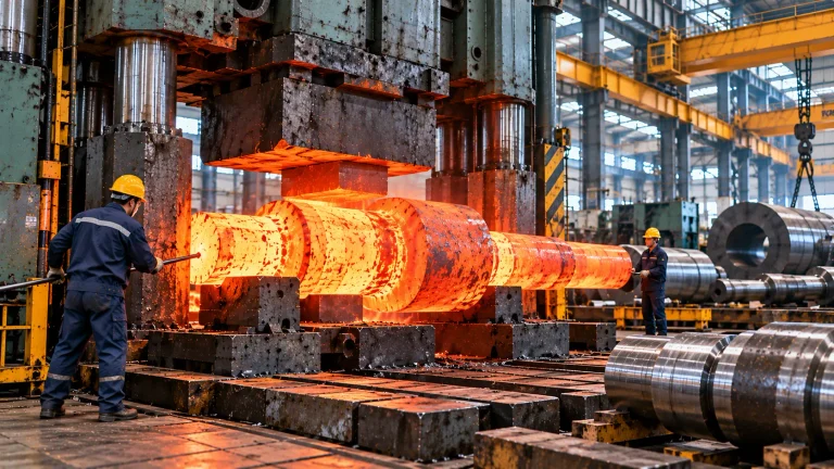
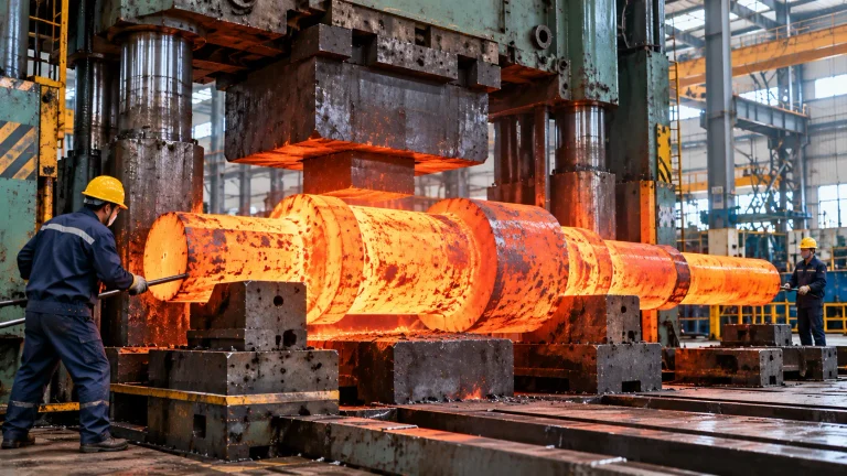
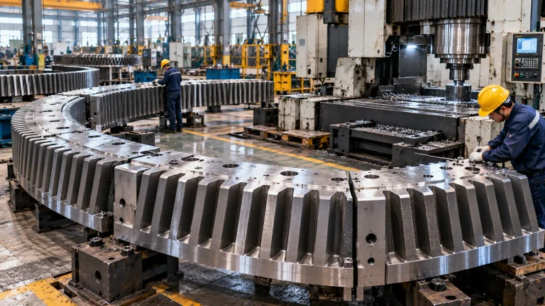
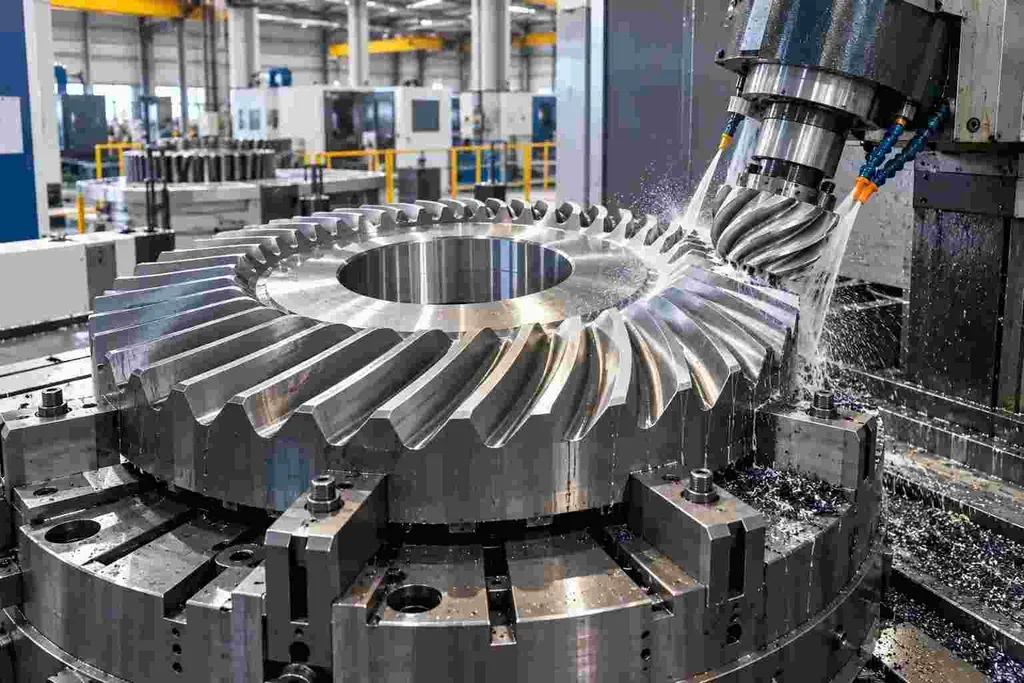
The gear manufacturing process for spiral bevel gears is more specialized than the process for many simpler gear types. The curved tooth shape usually requires dedicated cutting or grinding methods, followed by inspection to verify geometry and contact behavior. Depending on the application, gears may also be heat treated to improve wear resistance and load capacity.
A simplified process often includes:
Because spiral bevel geometry is sensitive, the pinion and gear are often treated as a matched set. Replacing only one component without confirming compatibility can create noise, poor contact, or premature wear.
Selecting a spiral bevel gearbox is not just a catalog exercise. The right choice depends on how the drive will actually operate, including load variation, starts and stops, shock loads, ambient conditions, and available mounting space. A compact gearbox may look ideal on paper but still fail to meet expectations if the housing, bearings, or lubrication system are not suitable for the duty cycle.
Before speaking with a spiral bevel gear manufacturer, gather the details that shape the design conversation:
For a spiral bevel gear reducer, pay close attention to overload conditions. Reducers are often chosen to multiply torque, which means tooth loading can be significant. If the application involves frequent reversing, sudden starts, or shock loads, those conditions should be discussed early rather than treated as afterthoughts.
A good spiral bevel gear solution feels almost uneventful in operation: it transmits motion smoothly, stays within expected temperature ranges, and does not produce unusual noise or vibration. That result depends on matching the gear design to the application instead of forcing a standard component into a demanding environment.
Look for these indicators when evaluating a gear set or gearbox:
A capable spiral bevel gear manufacturer should be able to help translate operating requirements into geometry, materials, tolerances, and inspection steps. The more complete your application information is, the easier it becomes to avoid undersized, noisy, or maintenance-heavy solutions.
Spiral bevel gearing is valued because it combines compact right-angle power transmission with smoother tooth engagement than many simpler bevel arrangements. Whether you are evaluating a spiral bevel gearbox, specifying a spiral bevel gear reducer, or reviewing a custom gear manufacturing process, the most important issues are load, alignment, lubrication, and tooth contact quality.
The best results come from treating the gear set as part of a complete mechanical system. When spiral gear design, housing accuracy, bearing support, and maintenance planning work together, a spiral bevel gear can deliver quiet, efficient, and reliable motion in a surprisingly compact space.
@ 2025-2026 Langteng Machinery